In high-stakes industries like lithium battery electrodes, optical films, and industrial adhesive tapes, the coating process is where profitability is won or lost. A single micron of deviation or a microscopic pinhole can lead to catastrophic batch rejection.
Drawing on decades of coating expertise, this guide provides a structured methodology to move from “random troubleshooting” to Precision Defect Management.
1. The Anatomy of Coating Defects
Accurate identification is half the battle. We categorize defects into three critical impact zones:
1.1 Appearance & Topography
Edge Beading (Thick Edges): Often caused by surface tension gradients (Marangoni effect).
Craters & Fisheyes: Typically a sign of surface tension mismatch between the coating liquid and substrate.
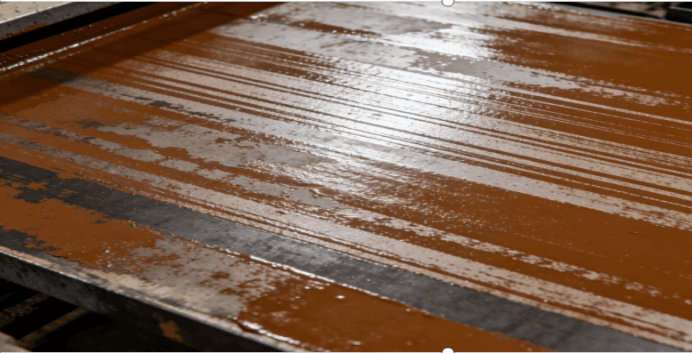
Streaks (Vertical/Horizontal): Usually linked to mechanical vibrations or particles trapped in the coating gap.
1.2 Functional & Performance Failure
Adhesion Loss (Delamination): Weak anchoring due to low substrate surface energy.
Thickness Non-uniformity: Stability issues in pump pressure or roller precision.
2. The 5-Dimension Root Cause Analysis
Most coating failures aren’t accidents; they are systemic deviations.
2.1 Materials & Rheology
Technical Insight: Success starts with the Weber Number and Capillary Number—the balance of inertial, viscous, and surface tension forces.
The Viscosity Trap: If your solid content is too high, you risk “heavy edges.” If it’s too low, you get “skinning” and poor coverage.
Contamination: Even 10-micron particles can cause catastrophic streaks in optical film coating.
Solution: Implement multi-stage filtration and ensure the substrate surface energy is at least 10 dyne/cm higher than the coating liquid.
2.2 Equipment & Mechanical Stability
Technical Insight: Precision coating requires sub-micron roller TIR (Total Indicator Runout).
Drying Profile: High initial heat causes “Skinning” (trapping solvent underneath), leading to bubbles and pinholes.
Web Tension: Fluctuating tension is the primary cause of coating misalignment and wrinkles.
3. KAWIN’S Structured Troubleshooting Protocol
When a defect appears on the line, follow this “Outside-In” sequence to minimize downtime:
Step 1: Fluid & Substrate Audit
Measure viscosity and temperature. Check for micro-bubbles. Verify the Corona treatment level of the base film.
Step 2: Mechanical Verification
Inspect coating rollers for debris. Check pump pressure stability and filter integrity.
Step 3: Process Parameter Fine-Tuning
Slow down the line speed by 10% to see if the defect disappears (indicates a leveling/drying issue). Adjust the drying oven airflow.
Step 4: Environmental Scan
Verify cleanroom particle counts and RH (Relative Humidity) levels. Static electricity is often the hidden culprit behind dust attraction.
4. Conclusion: From Reactive to Proactive
Coating is a “Chain Process”—it is only as strong as its weakest link. To achieve a 99%+ yield rate, manufacturers must shift from reactive fixing to proactive stabilization:
Standardize SOPs for material mixing and equipment cleaning.
Maintain equipment precision with regular maintenance cycles.
Invest in high-quality raw materials and stable environmental controls.
5.FAQ
Q1: Why do “craters” or “fisheyes” appear in my coating?
A: Craters are usually caused by surface tension imbalances. If the substrate surface is contaminated (oil/dust) or has a lower surface energy than the coating liquid, the liquid will “retract,” forming a crater.
Q2: How does humidity affect coating quality?
A: High humidity can cause solvent-based coatings to “whiten” or affect the drying rate, while low humidity (below 40% RH) significantly increases static electricity, leading to dust attraction and sparks.
Q3: What is the ideal surface energy for film coating?
A: As a rule of thumb, the substrate’s surface energy should be at least 38–42 dynes/cm for most adhesive systems to ensure proper wetting and anchorage.