Thermally Conductive Tape
Thin bonding between components and heat spreaders where attachment and heat transfer share one layer.

CUSTOM INDUSTRIAL TAPE SOLUTION
Build the solution around thermal path, bond line, electrical isolation, compression and assembly pressure, rather than specifying only a tape name or nominal thickness.
Quick answer: KAWIN customizes thermally conductive tapes, graphite-related laminations, silicone pads and foil-based heat-spreading parts. Material selection and converted presentation are aligned to the real component and production process.
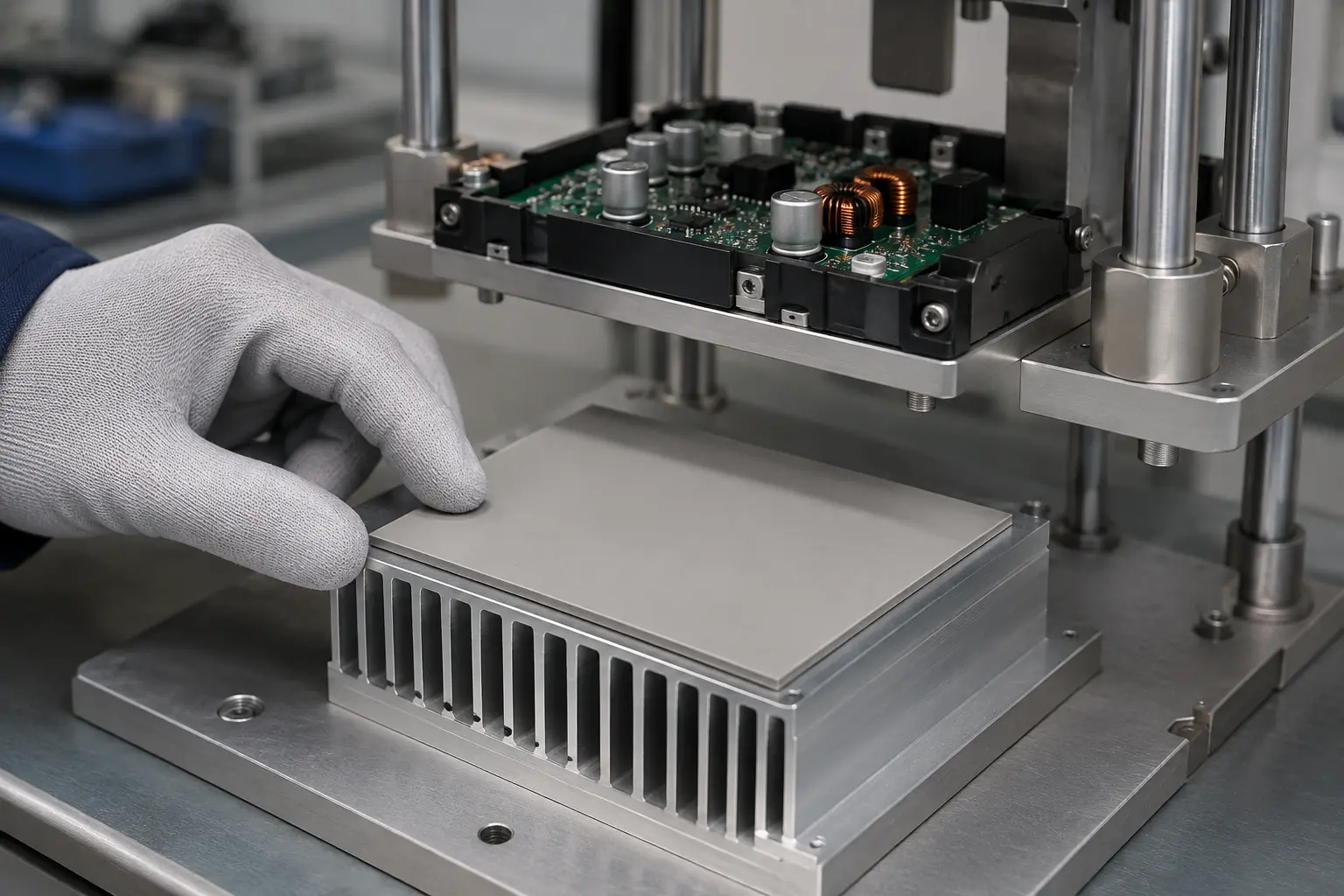
CUSTOMIZABLE PRODUCT FORMS
These options share one topic, but solve different engineering tasks. Select the closest form, then confirm the construction against your application.
Thin bonding between components and heat spreaders where attachment and heat transfer share one layer.
Compressible gap filling between uneven components and heat sinks.
In-plane heat spreading with protective films, adhesive layers and die-cut geometry.
Foil-based parts combining heat spreading, shielding or grounding functions.
Barriers and spacers used where heat flow must be controlled rather than increased.
Multi-layer thermal, dielectric and adhesive components supplied ready for assembly.
CONFIGURABLE PARAMETERS
The quotation becomes meaningful only when the critical construction and delivery variables are known.
APPLICATION-LED SELECTION
Use these scenarios to identify which details should be tested first.
Thin bond line and long-term adhesion must be balanced against heat transfer.
Electrical isolation, flame behavior, compression and service temperature all affect the stack.
Gap tolerance and mounting pressure influence tape versus pad selection.
Graphite orientation, edge protection and die-cut geometry become central.
RELATED CUSTOM SOLUTIONS
These links prevent an isolated page without turning the page into a directory of unrelated tapes.
CUSTOM THERMAL MANAGEMENT TAPE AND PADS FAQ
The best thermal interface is selected around the assembly stack, not conductivity data alone.
Thermal tape combines heat transfer with attachment for relatively controlled interfaces. A compliant thermal pad is generally considered when larger gaps, tolerance variation or compression are present. Mechanical retention and service conditions should be reviewed with either option.
No. Actual thermal resistance also depends on thickness, contact area, surface flatness, wet-out or compression, interface pressure and long-term stability. A thinner, well-contacted material can outperform a higher-conductivity material that does not fit the joint.
Selected constructions can combine thermal transfer with electrical isolation, but dielectric requirements, puncture risk, edges, mounting pressure and aging must be specified. Electrical insulation should be validated in the finished assembly.
Provide the component and heat-sink drawing, gap range, thickness, target thermal performance, voltage requirement, compression or mounting force, operating temperature, liner needs and placement method. Openings and keep-out areas should be clearly dimensioned.
Send the substrate, dimensions, service conditions and estimated quantity. We will identify the missing variables before proposing a construction.
Discuss this custom tape